 Back
Back (EN) User Guide Qvido
User manual for Qvido version 2.13.19. - Last updated January 01, 2022.

Thank you for using Qvido, a professional video centration system of Oaktree Technologies GmbH.
Qvido is used to determine optometric measurement values that are required to make spectacles to improve visual acuity. The system consists of a digital mobile app that runs on an iPad and a physical fitting frame. These two components can only be used in combination with one another. The product is used by trained opticians.

Unintended and improper use can result in hazards and damage. We therefore ask that you read these instructions for use carefully and follow them closely. Users of Qvido should always have these instructions to hand. Also note the safety instructions to avoid personal injury and damage to property.
If you have any questions regarding the content of these instructions for use or the use of the product, please contact your distributor.
Your Qvido Team
All versions of the instructions for use are available for download on our website or can be requested from the manufacturer: Help/Support
Manufacturer contact details:

Oaktree Technologies GmbH
Versmannstrasse 2
20457 Hamburg, Germany
Intended use
Medical purpose and clinical benefits
An optician determines specific centration data such as the pupillary distance and fitting height so that spectacles can correct a patient’s poor vision in an optimal manner, and this data is used as the basis for individually grinding the lenses so they are correctly positioned in the frame. Qvido provides very precise digital support for this process.
Spectacle centration refers to the optimal alignment between the optical main axis of the eyes (center of the pupil) and the optical axis of the corrective spectacle lenses. Even a slight deviation between the two axes impairs visual performance, and the object being viewed appears blurred or distorted.
The centration of all technical parameters to the main optical axis is one of the most important fine mechanical and optical tasks performed by an optician. If centration is not carried out precisely, even correction values that are ground into the lenses in an ideal way will tend to be disruptive rather than completely effective.
A patient’s centration data can also be determined manually. In this case, the pupil position is determined iteratively, with the optician marking it with a pen on both lenses and then using a manual visual check on both sides to verify whether the optical main axis of the eyes and the optical axis of the lenses are correctly aligned with one another. The values are adjusted in small increments until a certain degree of precision is achieved. Qvido provides experienced users with a good assessment of the position of the pupils, which significantly speeds up the centration process.
Qvido consists of a mobile app and a physical fitting frame that is attached to the patient’s glasses during centration. The Qvido fitting frame comprises a range of markers that provide support for calculating the centration parameters.
Indication
Qvido can be used for any optometric adjustment of glasses by an optician.
Contraindications and restrictions
In the case of half-eye glasses, small glasses for children, safety glasses, and bifocal lenses, only the PD should be determined with Qvido and the fitting height should be measured manually.
The optician should conduct a very careful plausibility check if patients have severe postural disturbances. The optician should always use their specialist knowledge to assess the subjective situation and make manual corrections where necessary.
Intended patient target group
People with defective eyesight who wish to wear glasses to correct this defective eyesight.
Intended users
The product must be used on the patient by an optician. The relevant specialists must be trained in the adjustment of spectacle lenses. Users must read the product-specific instructions from the manufacturer – an user manual and in-app help are available to provide the user with information on the correct use of the system.
Intended environment of use
Qvido can be used in an optician’s normal business environment. It is important to ensure that the environment is sufficiently lit.
Important safety instructions
IMPORTANT! Read all safety instructions carefully before using the product. Follow the safety instructions to avoid injuries.
The packaging material may have sharp edges. Be careful not to injure yourself on these edges. Prior to use, also make sure that no packaging material remains stuck to the frame. Remove all residue and clean the fitting frame correctly prior to initial use (see “Cleaning” section).
The fitting frame may not be used if it is incomplete or damaged. A description of the individual components can be found in this instruction manual in order to verify that the system is complete. Also ensure that the marker points are intact, clean, and easily recognizable.
Make sure that the fitting frame is attached to the spectacle frame as described in the instruction manual during use and that the grips and lock slides fit firmly and correctly. The fitting frame must not be bent as it would no longer be possible to use it correctly in this case. Also ensure that the spectacles are not subjected to excessive force. The spectacles could break and cause injuries.
Always store the fitting frame in the supplied protective case to prevent damage to the fitting frame.
Please clean the fitting frame before and after every use according to the instructions in the “Cleaning” section to ensure that no bactericidal or virucidal residue remains on the frame.
Check whether the fitting frame has any sharp edges prior to use. If so, this is due to a production error. The frame should not be used and should be disposed of.
It is important that the fitting frame is correctly and secured attached to the spectacle frame during use so that a precise measurement can be carried out and the patient is not injured.
The patient should put on the spectacles with the attached fitting frame themselves. Instruct the patient to do this carefully and close their eyes to prevent injuries.
If it is not possible to determine the desired optometric values for any reason, or if the measurement is interrupted, the measurement must be repeated. This also applies to procedures for which the captured photos are of poor quality.
If it is necessary or expedient to manually input or adjust certain values, ensure that these values are valid and correct from an optical perspective. Always carry out a manual review of the results each time you use the system and ensure that the results are technically accurate in relation to the patient.
Reporting obligation
Notify the manufacturer and the competent authority of the EU Member State in which you are located of any serious incidents (damage, injuries, infections, etc.) that occur in connection with the product.
The competent authority in Germany is the Federal Institute for Drugs and Medical Devices (BfArM). You can find current contact information on the BfArM website: bfarm.de.
Description of the product
Functional principle of the product
Qvido consists of a digital app installed on an iPad and a physical fitting frame. To determine the centration data, the optician attaches this fitting frame to the spectacles selected by the patient. The patient puts on the spectacles with the fitting frame attached to the spectacle frame, and the optician uses the app to create images of the patient from the front and side. The optician then determines the following optometric parameters via the app:
- Pupillary distance – left and right
- Sight height – left and right
- Corneal distance
- Pantoscopic angle
- Frame wrap angle
- Lens height and lens width
- Lens diameter
The app is designed to be very simple and user friendly and supports the optician in determining the parameters on the basis of a pre-defined procedure and intuitive functions.
The values determined with the app can be transferred to an external system via a generic interface. This transfer is carried out automatically via a generic interface that can be individually adapted by the user’s IT department to suit its systems. All data and images are deleted after the values have been transferred. A new application can be started.
Product conformity
The product fulfills the following regulatory requirements of MDD 93/42.
Scope of delivery and spare parts
Oaktree Technologies supplies the following components for Qvido:
- Qvido app (digital via download)
- Qvido fitting frame (physical component by delivery)
Required components
- An iPad of the supported devices with an installation of the latest Qvido app according to Systems Requirements
- The Qvido app is made available by Oaktree Technologies as a digital download in the customer’s App Store Connect. The information required for the download and installation are provided to the customer’s IT department following conclusion of the contract.
- The Qvido fitting frame is physically sent to the customer:
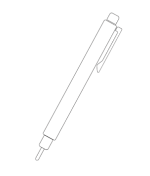
- A soft-tipped marker to mark the visual point in the lenses of the spectacle (not included in the scope of delivery):
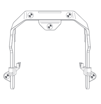
The Qvido fitting frame
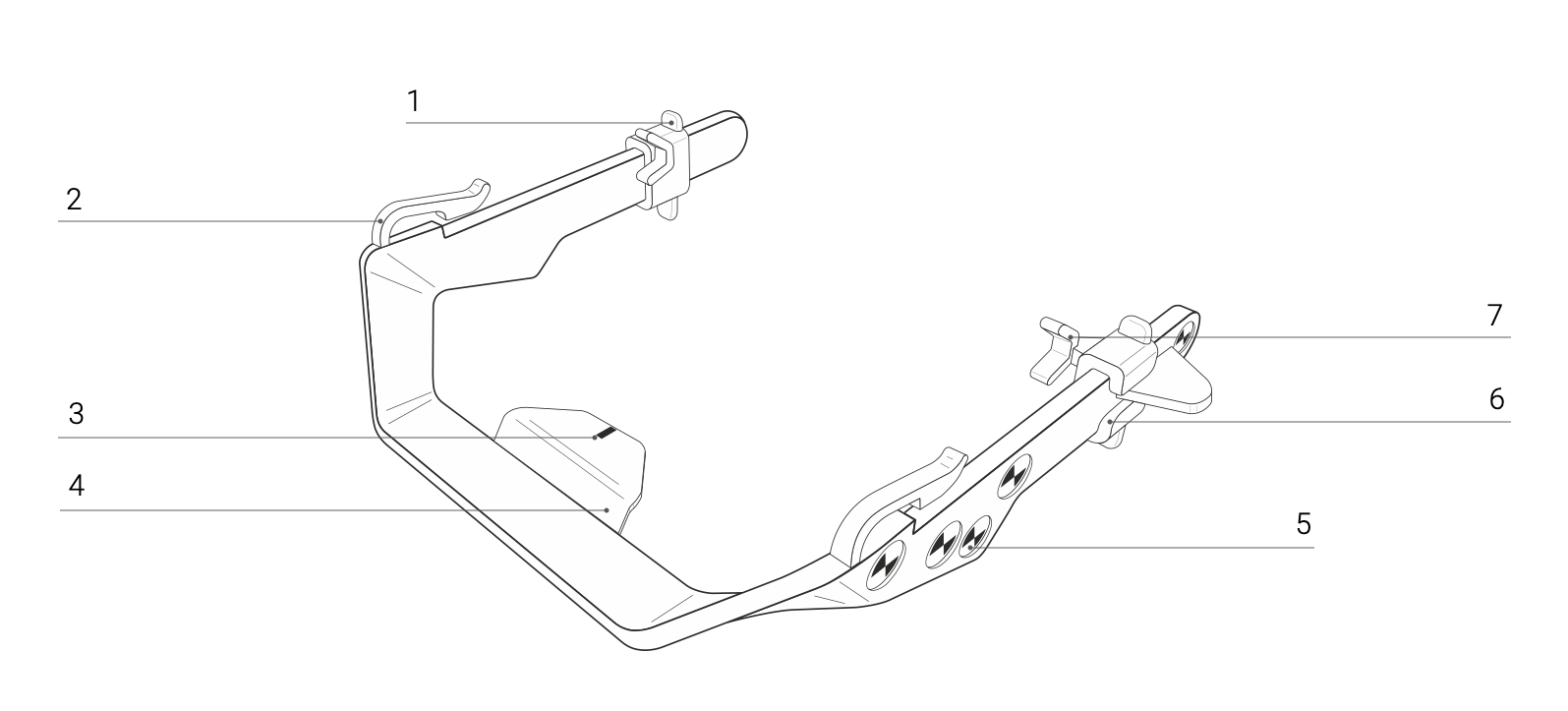
Components:
- Grip
- Frame Clip (including upper rubber sleeves)
- Centre Indicator Chart
- Crossbar
- Markers
- Lock Slide
- Frame Holder (including lower rubber sleeves)
Packaging dimensions and weight of the fitting frame
| Category | Specification |
|---|---|
Packaging dimensions, fitting frame (H x W x D)`` |
14 x 14 x 4 cm |
Weight including packaging |
30 g |
Storage of the fitting frame before and after use
- Always place the fitting frame in the supplied protective case. Keep both components in a safe place.
- The fitting frame is a delicate measuring instrument. If it is bent or damaged, it could lead to inaccurate measurement results.
- Also ensure that the marker points are clean and easily recognizable. This is the only way to achieve an accurate measurement.
Spare parts
The upper rubber sleeves of the grip and the lower rubber sleeves of the lock slides are available for ordering as spare parts:
- Upper rubber sleeves; article number 010
- Lower rubber sleeves; article number 020
Instructions: Carefully pull off the old sleeves if they are still attached to the fitting frame. Carefully slip the new sleeves onto the grips or onto the lock slides. The rubber sleeves are simply slipped on and then remain in place due to their material properties.
Initial setup
Installation
The Qvido app is delivered digitally and can be installed on any supported iPad. For details of the current system requirements as well as requirements for the network environment, see:
System Requirements
Access to download the app is managed on a customer-by-customer basis and is provided by the manufacturer depending on the corresponding contractual arrangements. The installation can be carried out by anyone using the iPad who has access to the contract details.
If the customer has requested an integration of an individual order system, the determined centration parameters can be transferred automatically via a generic interface. Connecting to the interface is described here: URL Scheme Documentation
The connection can be performed by an IT expert who knows how to adapt interfaces.
If you have further questions regarding the download, installation, and connection to downstream systems, please contact your internal IT support.
Removing the transport bracket and packaging of the fitting frame
Before using the fitting frame for the first time, remove and dispose of the packaging and the enclosed cardboard templates provided as a means of protection during transport. Keep the plastic protective case included in the packaging as this is used to safely store the product.
Always place the fitting frame in the supplied plastic protective case intended for this purpose. Keep both components within reach. Ensure before use that the marker points are intact, clean, and easily recognizable. This is the only way to achieve an accurate measurement.
Verifying proper functionality
The Qvido app has been properly installed when it displays the following start screen:
Help function

Context-sensitive help for each application step can be called up at any time via the help button (?) at the top left. The help can be exited again via the close button (x) at the top right.
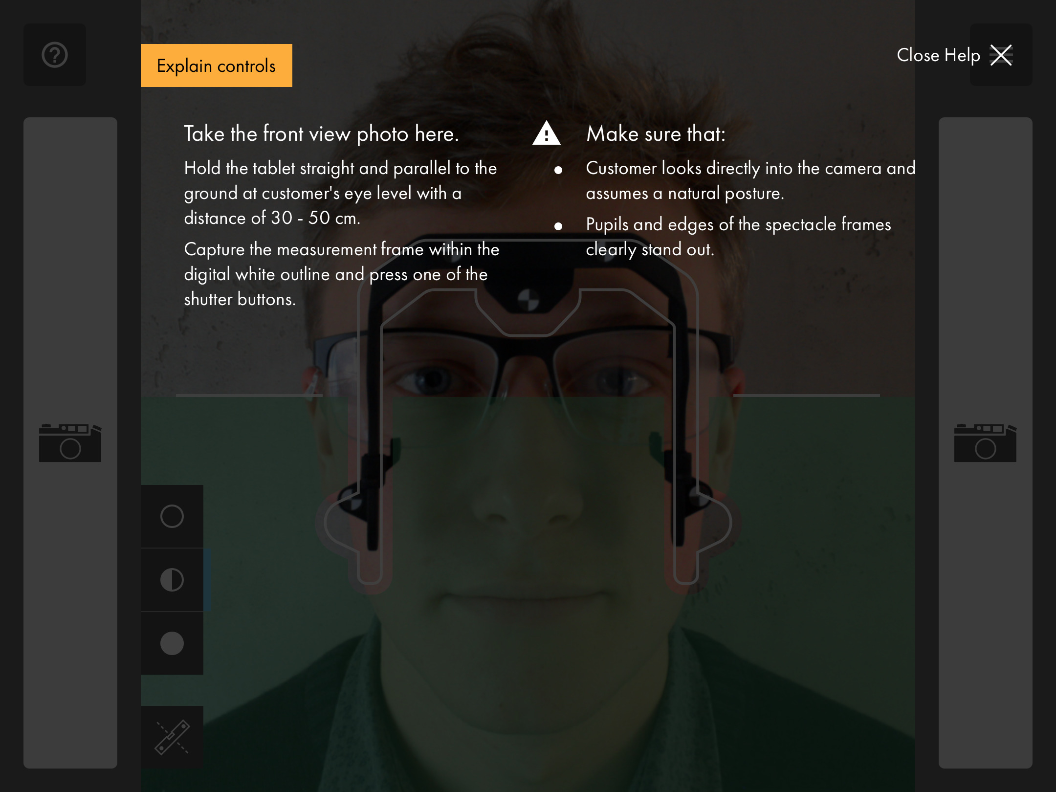
With "Explain controls" you can call up further information on the individual controls.
Information about the app

Further information and functions are available via the menu icon at the top right:
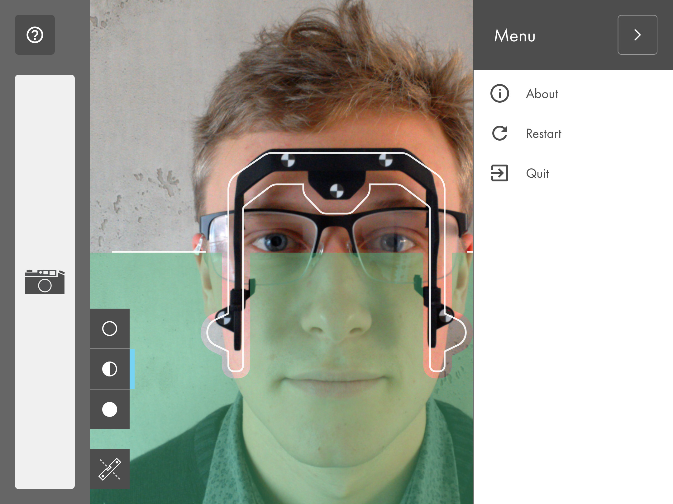
- About: Details about the current version and provider of the app.
- Restart: The current measurement is canceled and a new process is started.
- Quit: The app is closed. Any existing values are not saved.
Preparation and workflow
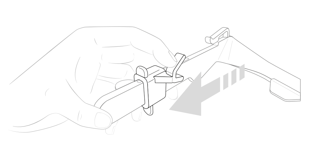
Attaching the fitting frame to the spectacles
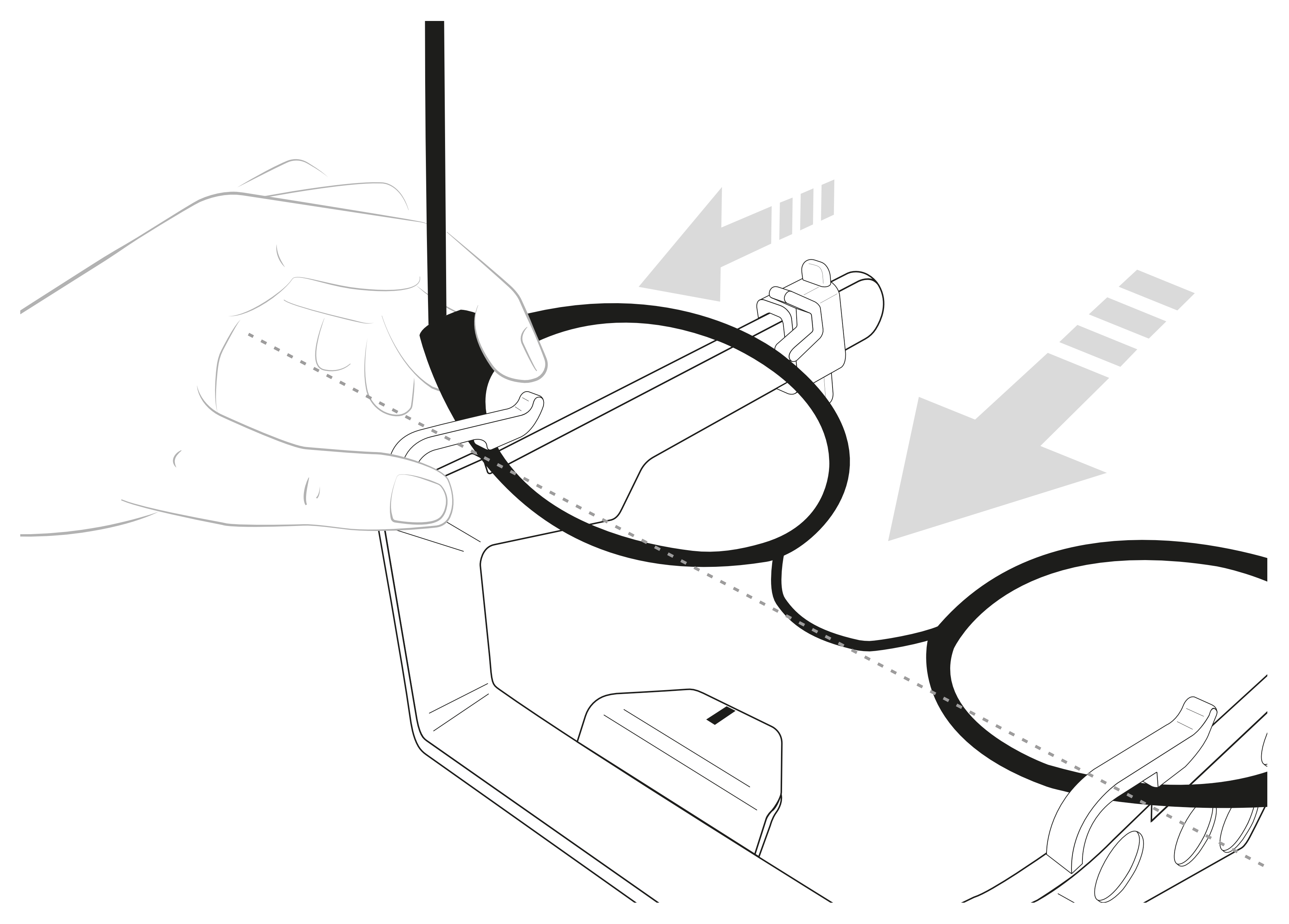
- Before attaching the spectacles, please move the lock slide in the direction indicated until it stops:
- Hold the fitting frame by the crossbar with the front facing downward:
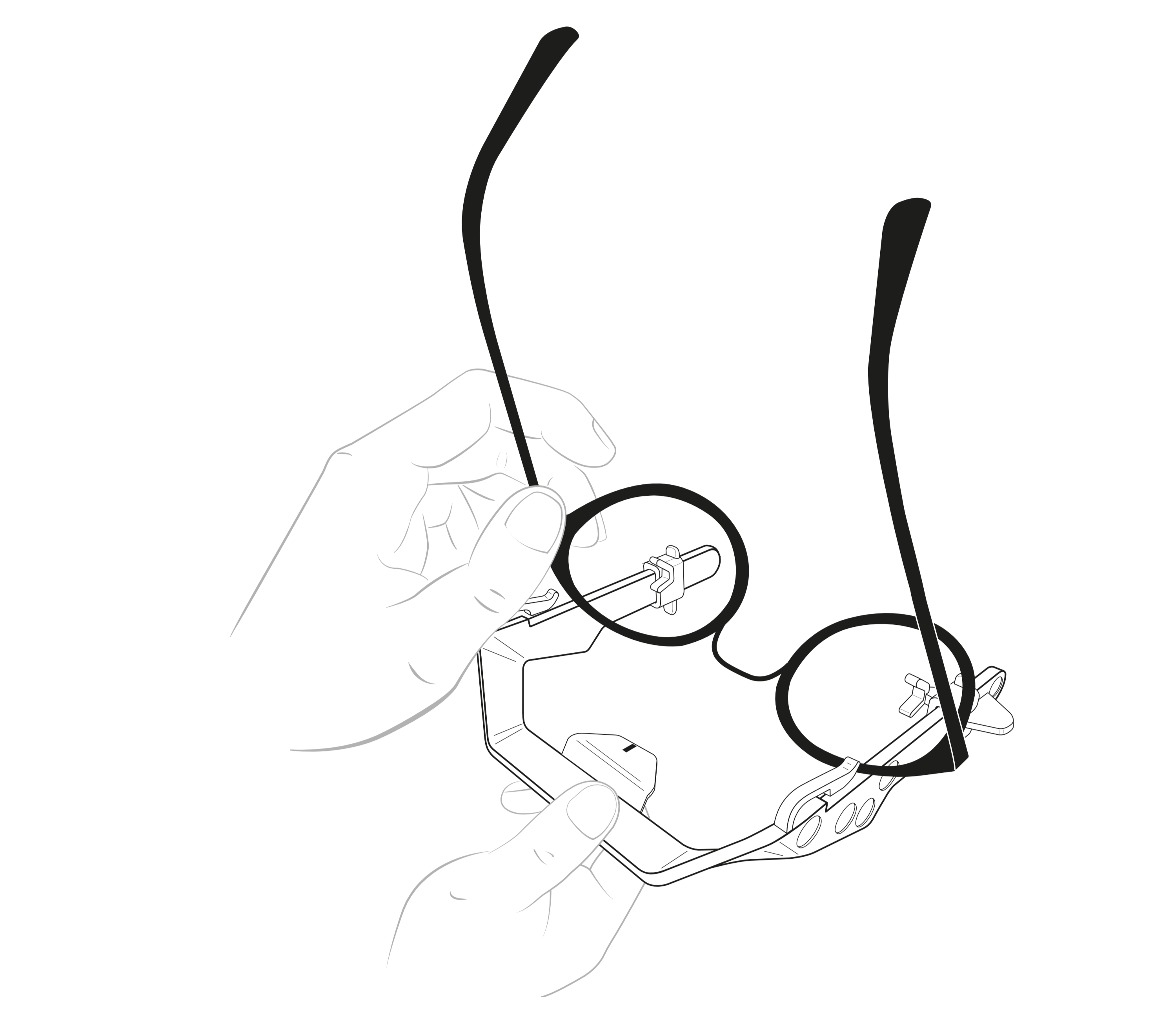
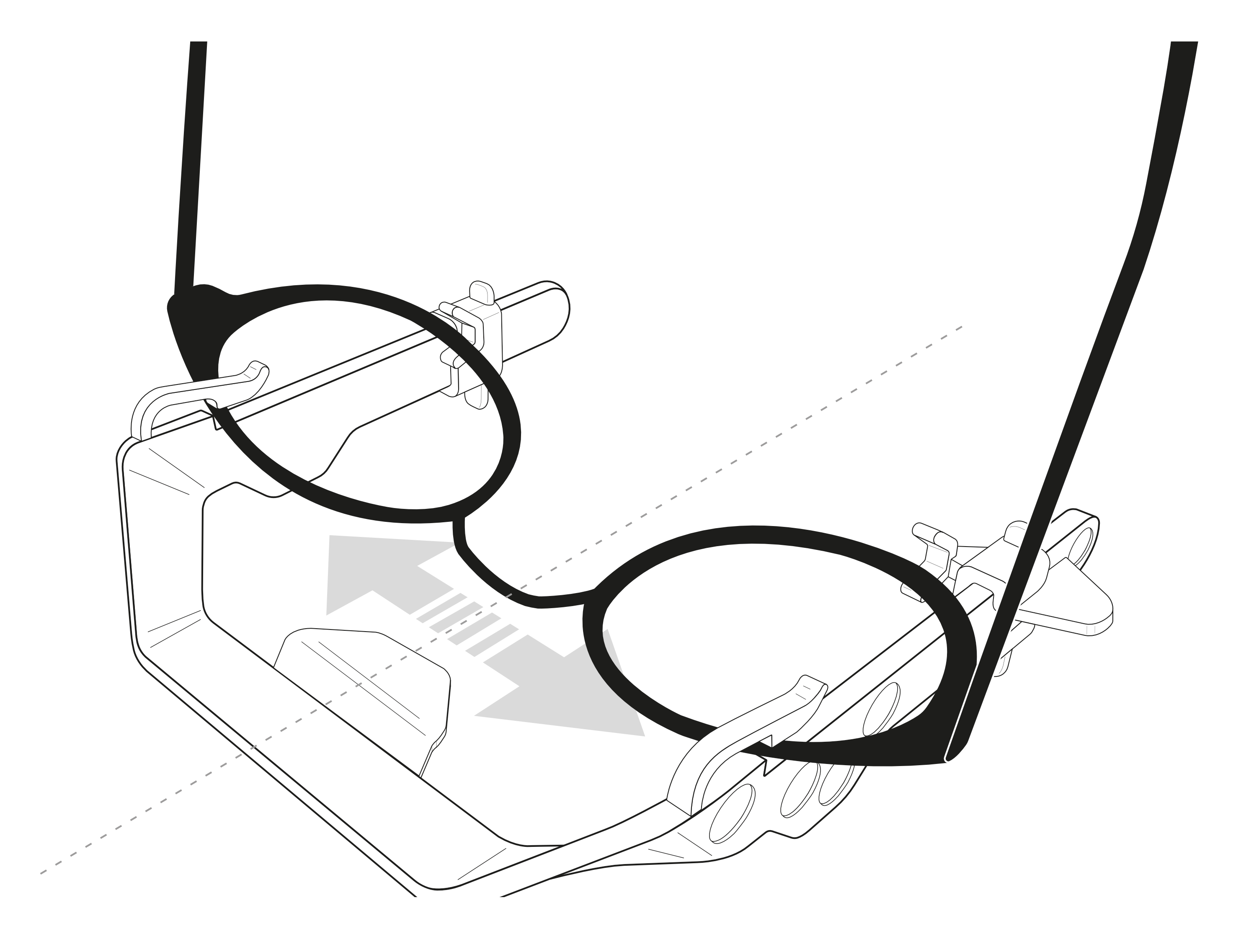
- Push the spectacles underneath the clip until the bridge reaches the top of the fitting frame:
Note: Depending on the thickness and size, it can be easier to insert the spectacle under the clip by slightly tilting the bridge forwards
- Align the centre of the bridge of the spectacles with the centre indicator:
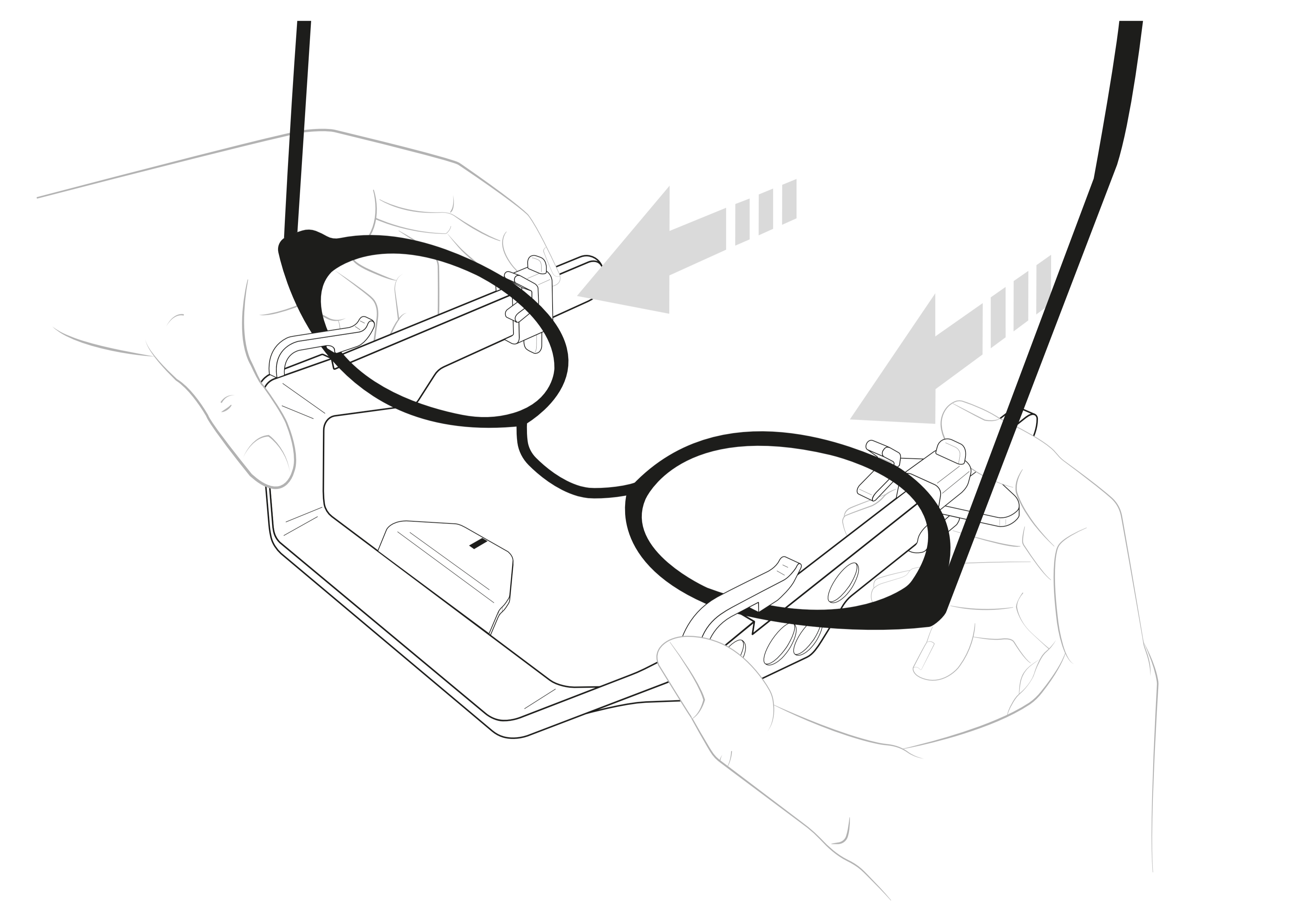
- Lock the spectacles into position by carefully pushing the lock slides in the indicated direction:
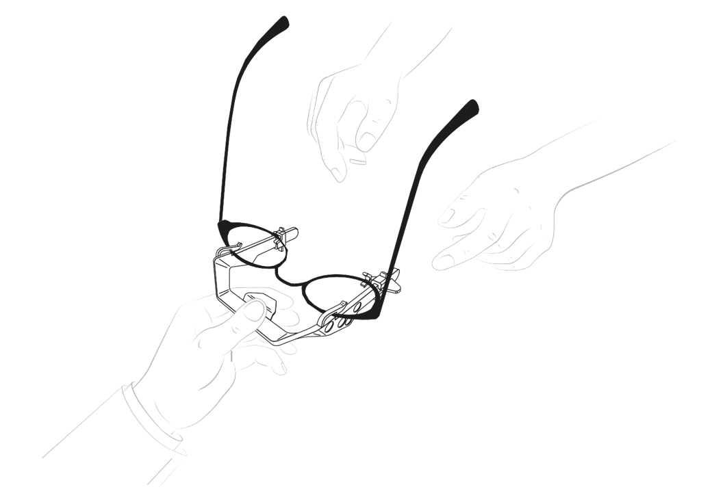
- Hand over the fitting frame including the spectacles to the customer, so that he or she can put them on comfortably by himself/herself:
- After the customer has put on the spectacles with the fitting frame, please check if the fitting frame is still aligned to the centre of the bridge of the spectacles. Also verify whether or not any markers are covered:
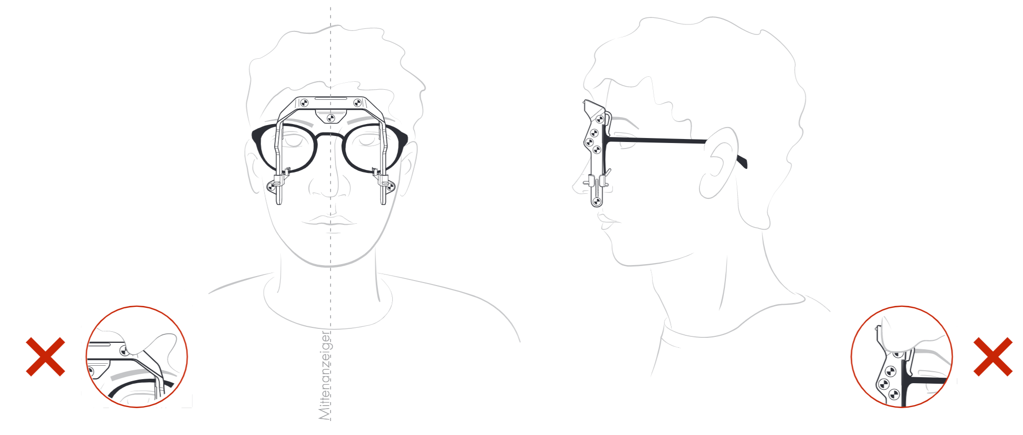
Note: Make sure that the glasses are straight and fit correctly and that the customer assumes his or her natural posture.
Aligning the tablet correctly
To be able to activate the shutter button, the tablet must be brought to a vertical position when shooting, perpendicular to the floor. To help you do this, an artificial horizon element in the interface is placed above the image.
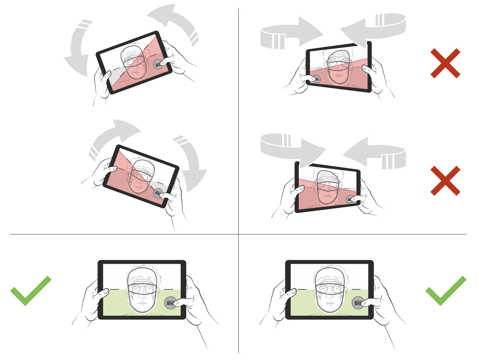
The artificial horizon reacts to the tablet turning around its horizontal axis. Turning the tablet around its vertical axis has no effect on the artificial horizon.
If the tablet is not perpendicular to the floor, the artificial horizon element is highlighted red and the shutter buttons become inactive. If the tablet is perpendicular to the floor, the artificial horizon element is highlighted green and the shutter buttons are free to be used.
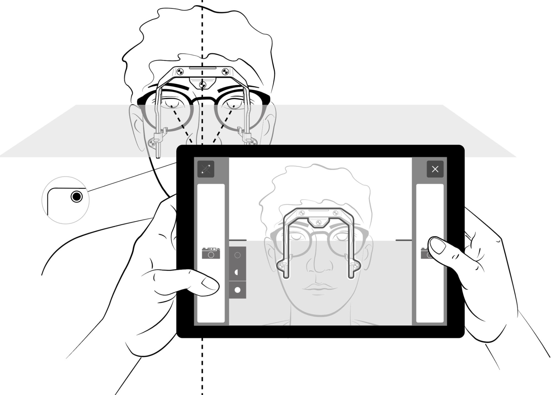
Note: The tablet will be off-center in relation to the customer because the tablet’s camera is located in the top right corner (from the customer’s point of view).
Taking the front view
Front view - Position to the customer
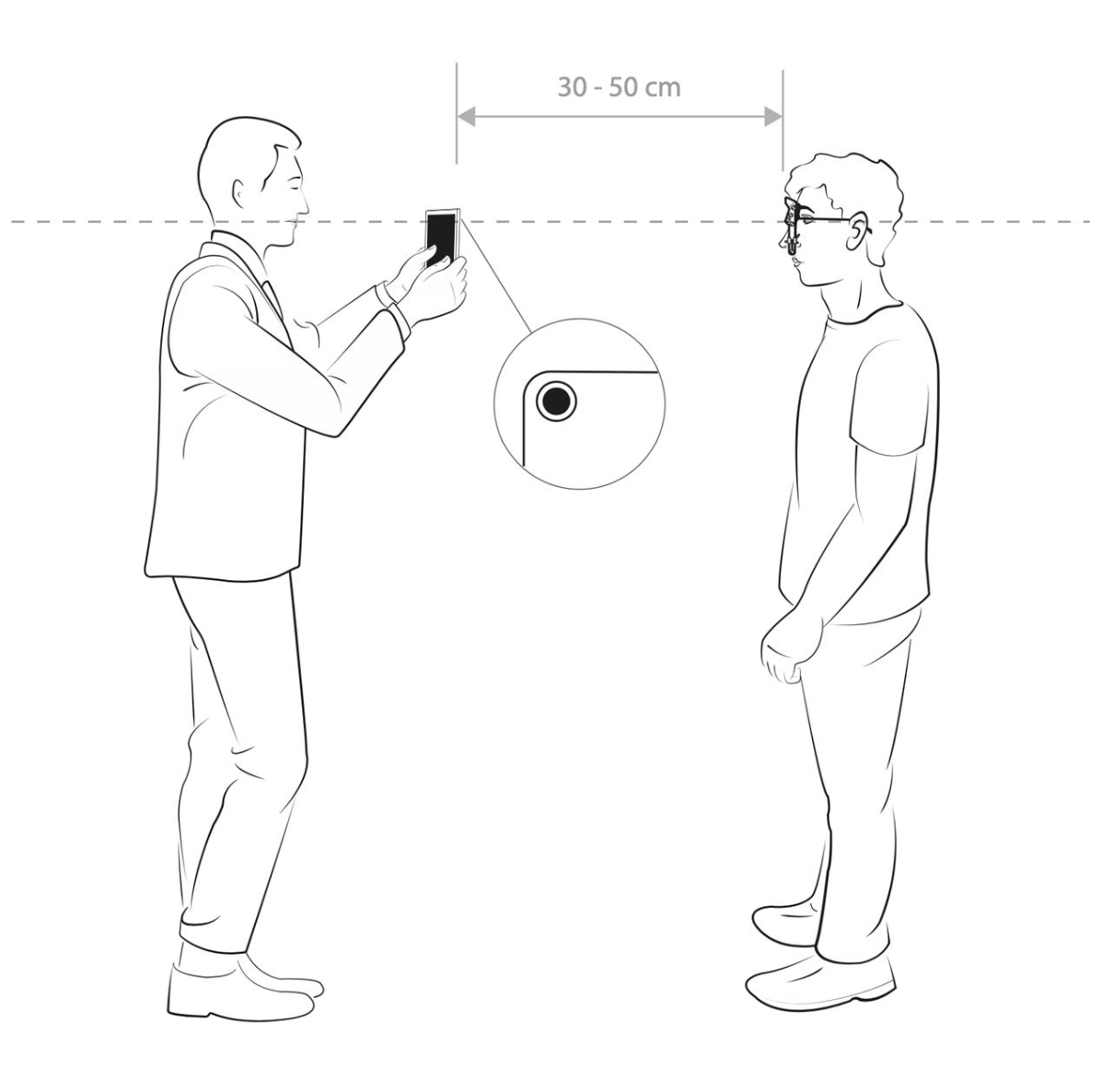
- Facing the customer, position yourself so that the rear of the tablet has a distance of 30 - 50 cm to the customer. Move the top edge of the tablet to the customer’s eye level.
- The customer must look directly into the camera in the upper right corner (from his point of view).
- Please make sure the customer assumes his or her natural posture.
Note:
- Important: To ensure ideal measuring results, the customer must be looking directly into the camera.
- Do not worry about the customer’s convergence. The system is able to balance that out mathematically.
- If the customer’s physical constitution requires so, the measurement can also be conducted sitting down.
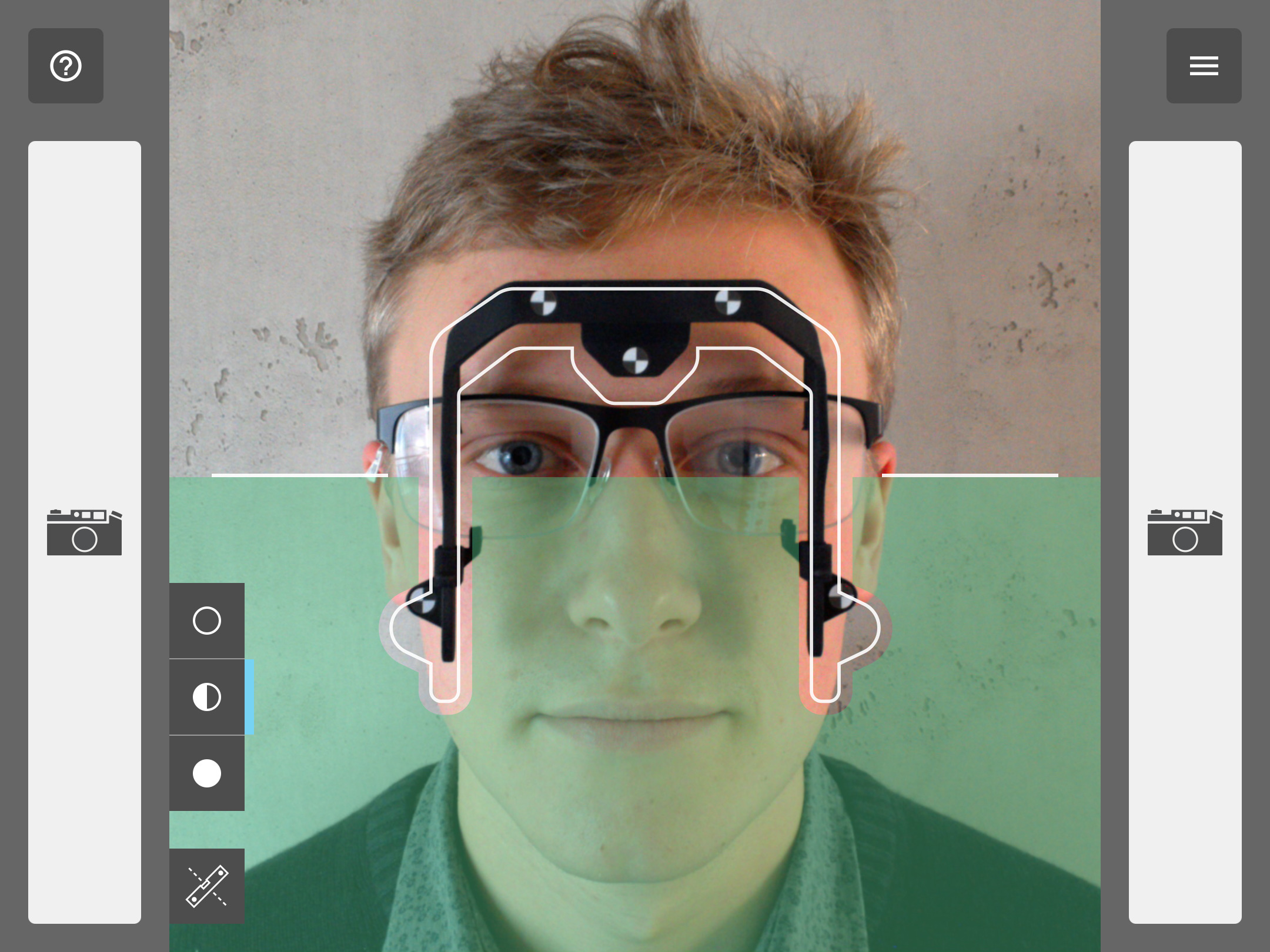
Front view - Use of the template and the shutter button
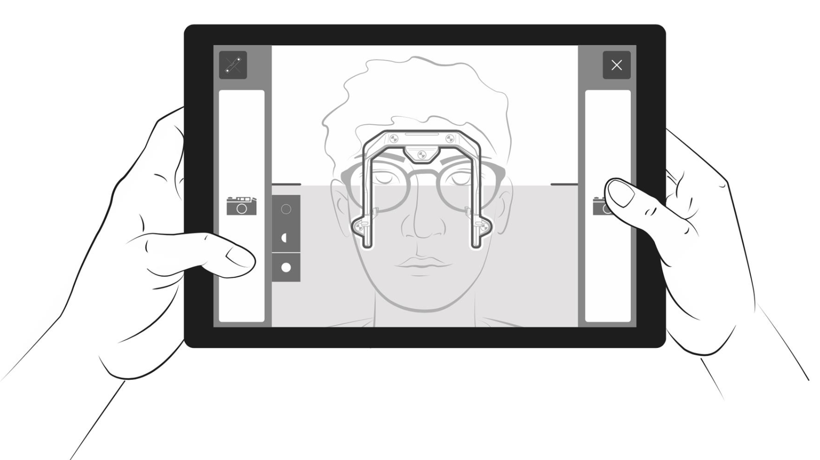
- With the tablet, position yourself so that the customer’s head is approximately located in the centre of the screen.
- Then, capture the fitting frame within the digital outline of the template of the tablet by moving the tablet either towards or away from the customer or slightly to the left or right.
- Level out the tablet (refer to “Aligning the tablet correctly”) and press the shutter button
Note:
- It suffices if the outline of the fitting frame approximately matches up with the template. A slightly blurred photo is also not a problem.
- The shutter button can only be activated if the artificial horizon element of the interface is stable and green (refer to “Aligning the tablet correctly”).
- Make sure you do not tilt the tablet forwards or backwards.
Taking the side view
Side view - Position to the customer
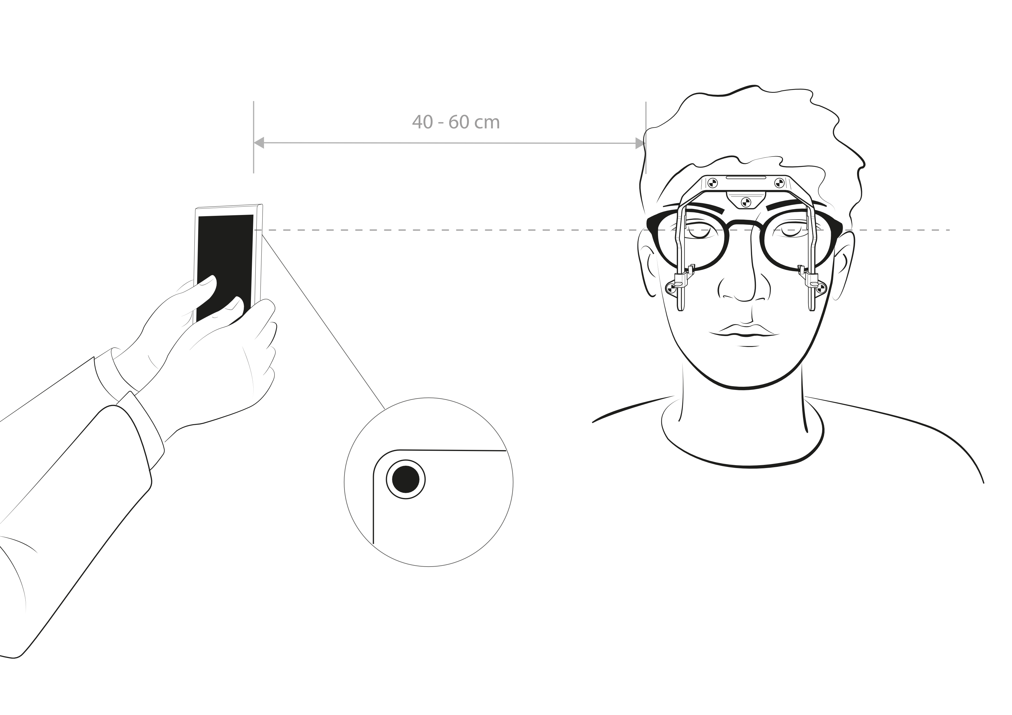
- Kindly ask the customer to hold his or her position after the front view photo was taken. Explain to the customer what you will be doing next.
- Position yourself in an approx. 90° angle to the customer.
- Then, position yourself so that the rear of the tablet has a distance of 40 - 60 cm to the customer. You can choose which side you prefer by pressing the mirror button. Move the top edge of the tablet to the height of the customer’s temples.
- Kindly ask the customer to further look straight foward into the distance.
Side view - Use of the template and the shutter button
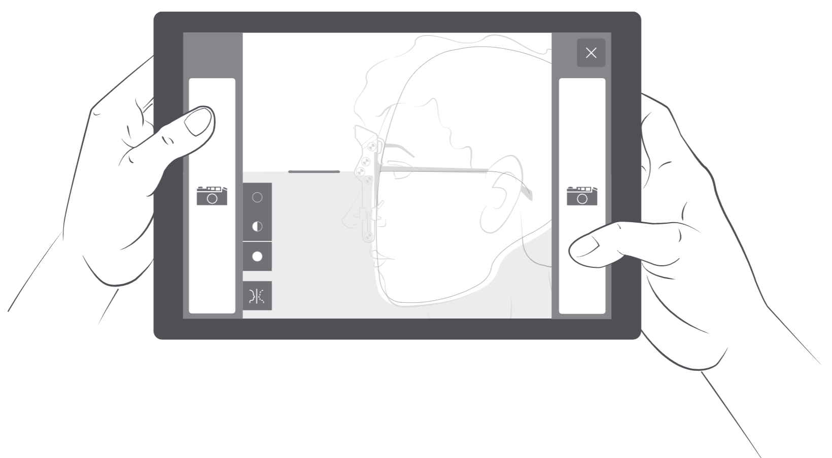
- Capture the customer’s head with the outline of the template on the tablet screen by moving towards or away from the customer with the tablet or by moving slightly to the right or left. Align the template’s drawn temple with the the temple of the customer’s spectacles.
- Make sure that the customer is still assuming his/her natural posture.
- Level out the tablet (refer to “Aligning the tablet correctly”) and press the shutter button
Note:
- You can mirror the template at any time for the side view photo.
- It suffices if the outline of the customer’s face approximately matches up with the template. Slight blurring is also not a problem.
- The shutter button can only be activated if the artificial horizon element of the interface is stable and green (refer to “Aligning the tablet correctly”).
Conducting the measurement
Accelerometer sensor calibration
- If necessary, the software opens the calibration automatically.
- The accelerometer sensor helps the tablet be leveled when taking pictures.
- The application automatically continues to “take front view photo” after a successfully executed calibration.
Place the rear side of the tablet onto a flat and ground-leveled surface and start the calibration.
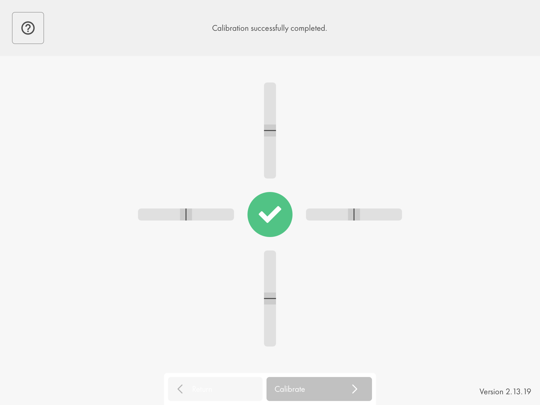
This calibration cross shows the status of the acceleration sensors for each axis:
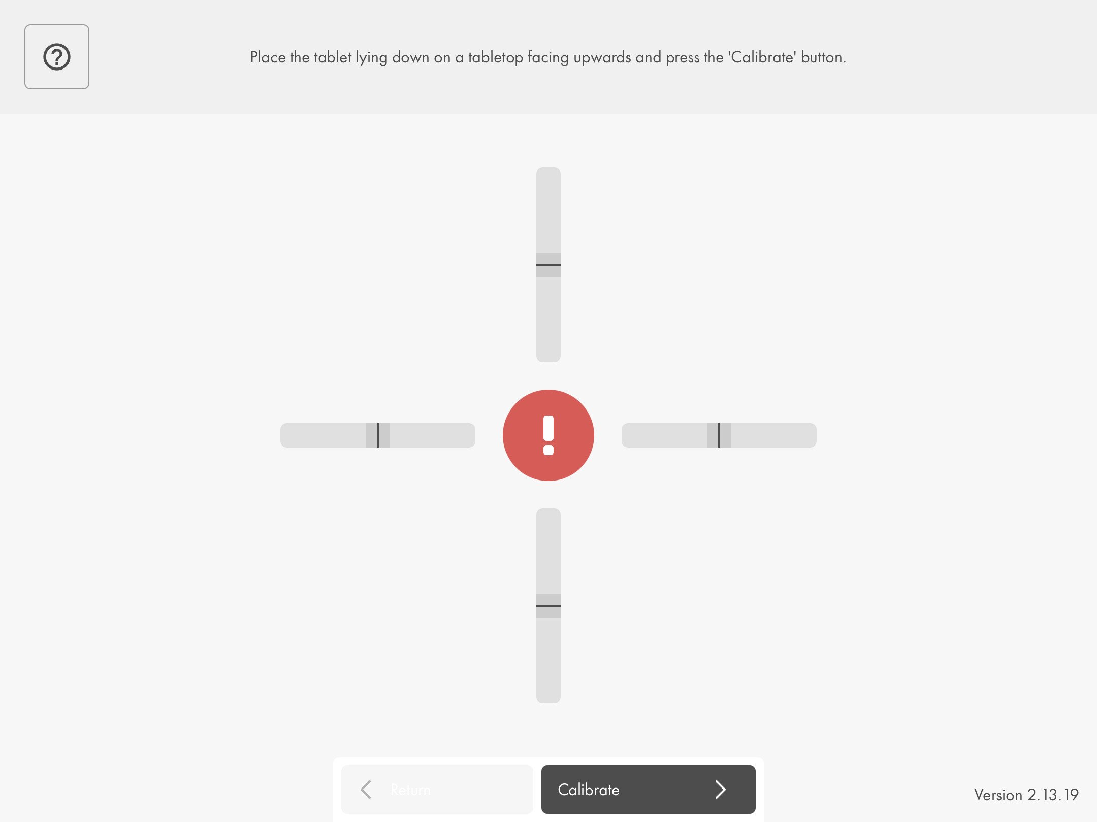
The calibration is completed when the calibration application changes its colour from red to green:
Taking the front view photo
Buttons
Acceleration sensor calibration: return to the accelerometer sensor calibration to recalibrate tablet. Use in case of odd behavior of the artificial horizon.

Shutter buttons: The photo is taken by pressing only one of these buttons.
Note: To be able to activate the shutter button, the tablet must be in a vertical position, perpendicular to the floor when taking the photo.

Contrast: Increase/reduce brightness of image:
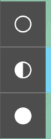
- decrease brightnes
- standard brightness
- increase brightness
It is difficult for the tablet’s camera to automatically regulate the brightness under certain lighting conditions. This can result in photos of the customer, which have severe shading in the area of the eyes. The visibility of the pupil, the frames and the fitting frame can be increased by using the Contrast buttons.
Note: A clear recognition of the eye area is important for a precise measurement. Particularly the pupils and the edges of the spectacle frames should clearly stand out.
Checking the front view photo
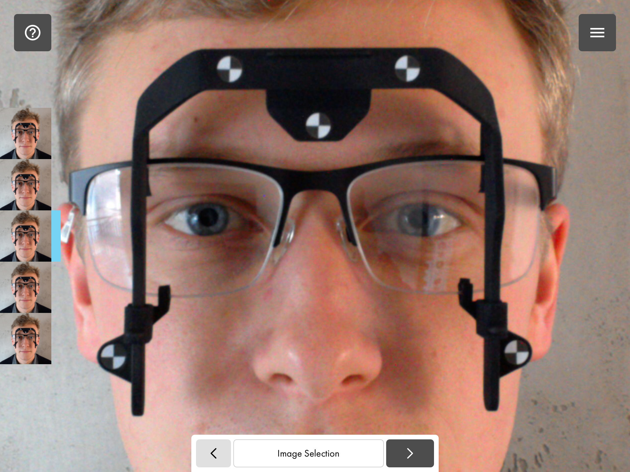
When taking the photo, continuous shooting is executed (5 photos). If the first suggestion for a measurement does not suffice, select the best alternative. Please select a photo in which the customer is not blinking.

Click “Continue” to let the system validate your selected photo and proceed to the side view:
Taking the side view photo
Use the white line template to determine the tablet position relative to the customer’s head.
To be able to activate the shutter button, the tablet must be in a vertical position, perpendicular to the floor when taking the photo. You are supported by the artificial horizon element again.
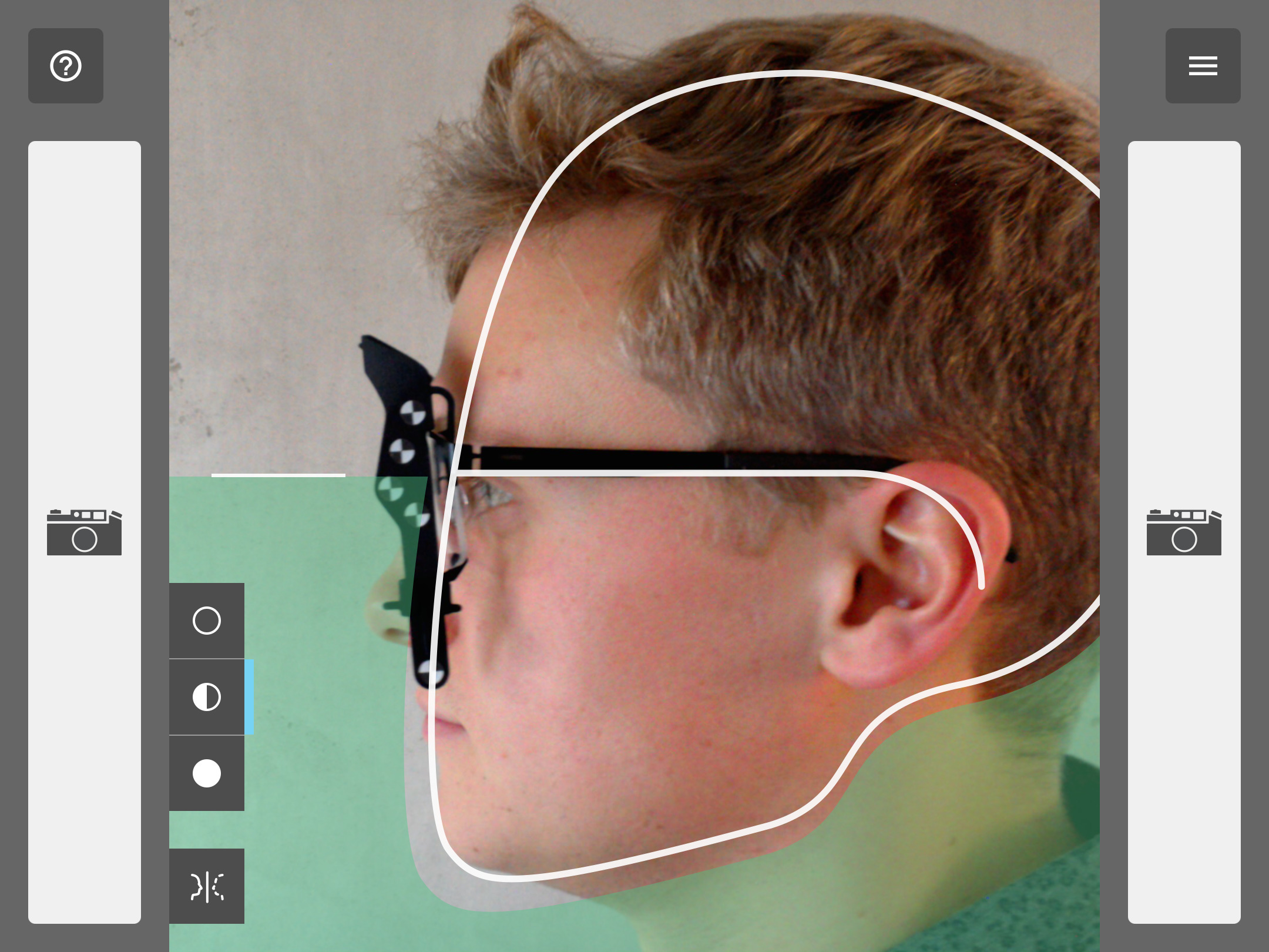
Note: A clear recognition of the eye area is important for a precise measurement. Particularly the eye should clearly stand out.
Buttons
Contrast: Increase/reduce brightness of image:
- decrease brightness
- standard brightness
- increase brightness
It is difficult for the tablet’s camera to automatically regulate the brightness under certain lighting conditions. This can result in photos of the customer, which have severe shading in the area of the eyes. The visibility of the pupil, the spectacle frames and the fitting frame can be increased by using the Contrast buttons.

Mirroring the template: In order to be able to take the side view photo from the left or right side of the customer, the template can be mirrored to suit the customer’s profile using this button.
Checking the side view photo
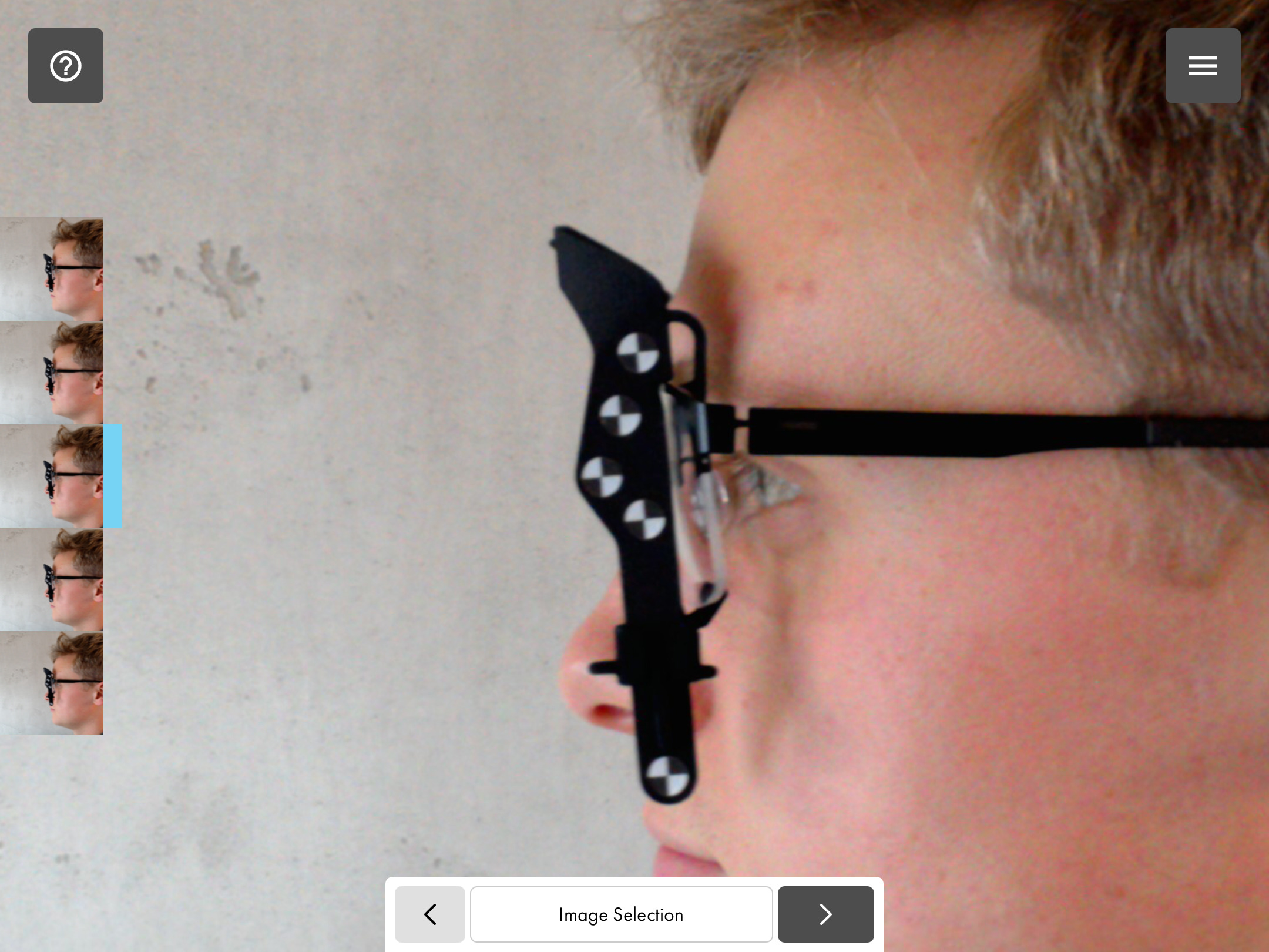
When taking the photo, continuous shooting is executed (5 photos). If the first suggestion for a measurement does not suffice, select the best alternative.
Click “Continue” to let the system validate your selected photo and proceed.
Determining the spectacles type
To ensure the lens groove can be considered in the centration of the lenses, select the type of spectacle (metal, rimless, nylor or plastic).
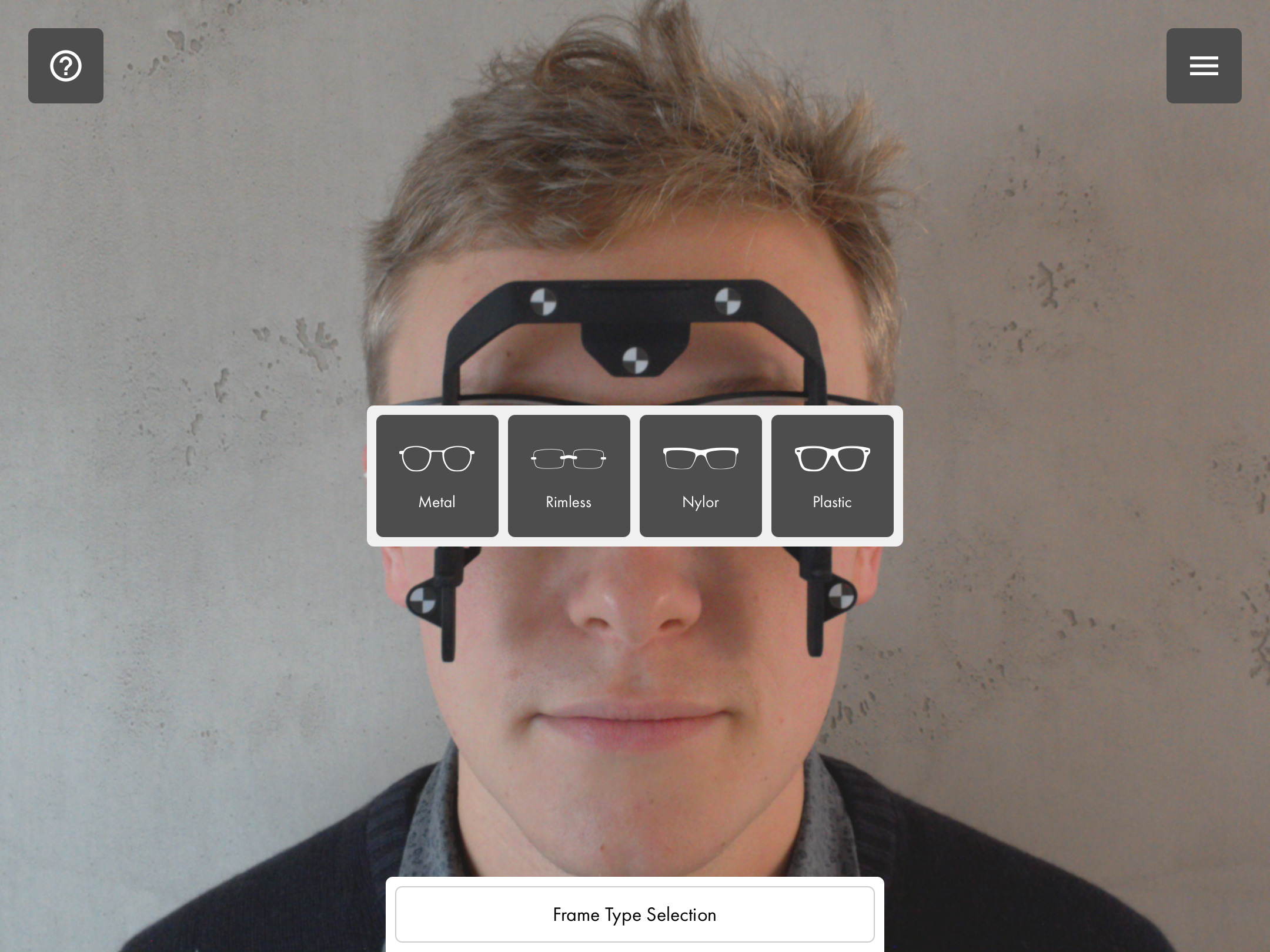
The software then automatically proceeds to “Determining the pupil”.
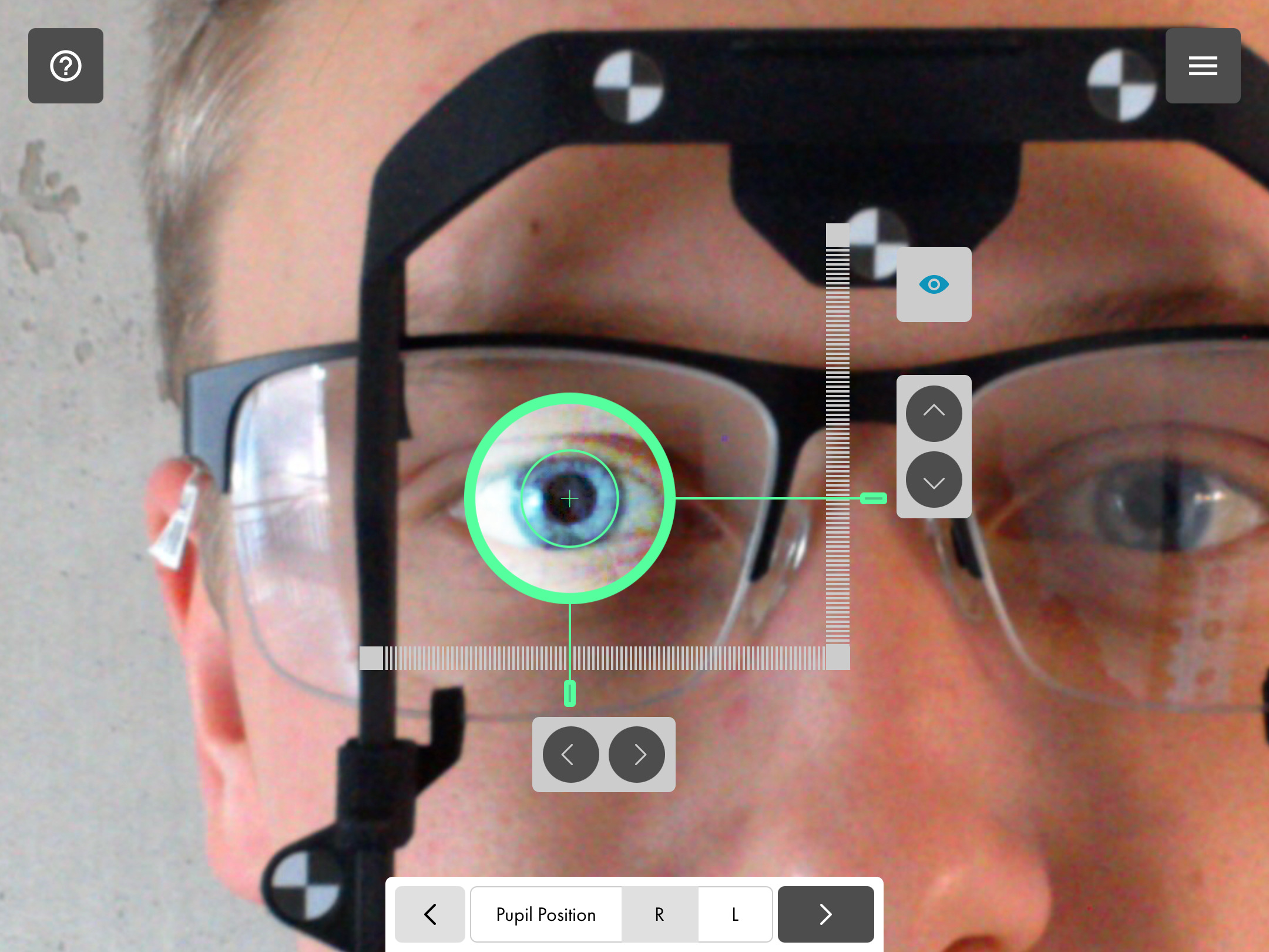
Determining the pupil - right & left
Functions
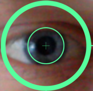
To determine the pupil distance, capture the eye with the green ring, position the green cross on the centre of the pupil by dragging the ring. For rough positioning of the indicator, you can directly move the needles in the horizontal and vertical axis of the ring by touching them.

Filter: If the pupil is difficult to distinguish from the iris in the photo, the content of the ring can be displayed without contrast boost by pressing this button.
Pointers/Ruler : Alternatively, you can touch each of the needles and move the horizontal or vertical axis roughly towards the direction of the centre of the pupil. By tapping directly on one of the rulers, the ring and needle jump to the position touched on the selected axis.

Arrow keys: By tapping the arrow keys, the centre of the pupil can be precisely determined horizontally or vertically in even finer steps.
Determining the rims - right & left
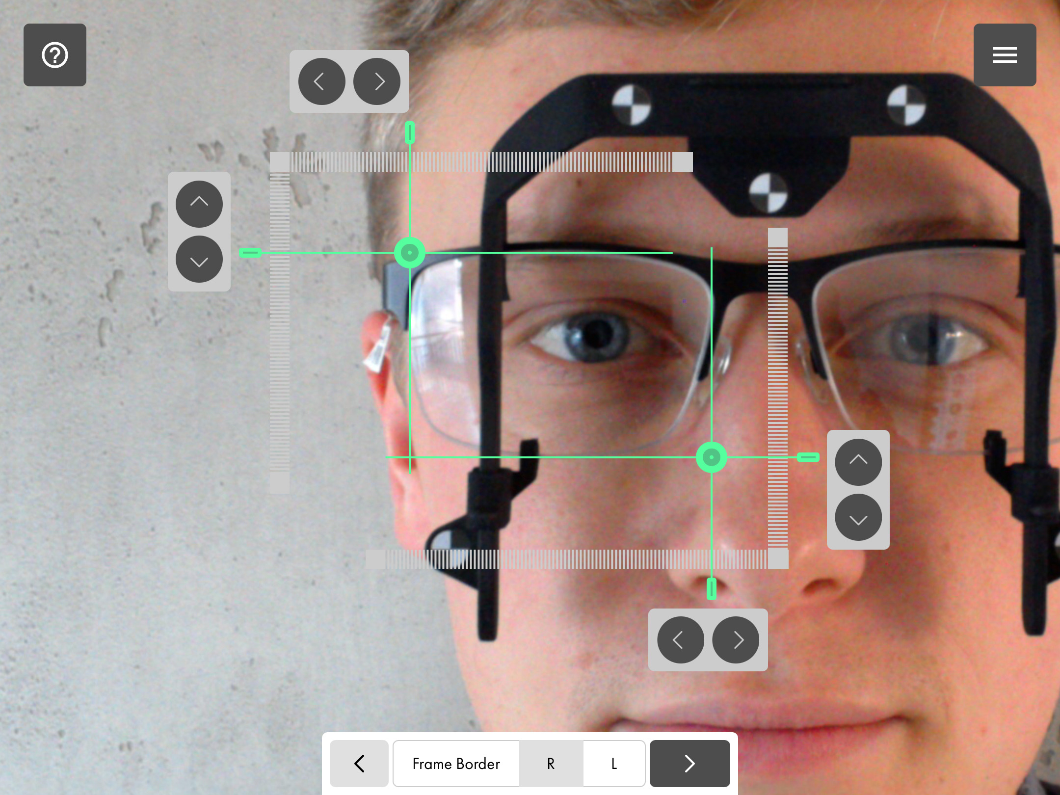
Determine the rims by marking all inner edges of the spectacle frames as precisely as possible with the needles.

Use green indicators: For a rough positioning, you can directly push the horizontal and vertical axis of the connected needles together with your finger after touching them.
Pointers/Ruler: Alternatively, you can touch each of the needles and move the horizontal or vertical axis roughly towards the direction of the inner edge. By tapping directly on one of the rulers, the corresponding needle jumps to the position touched on the selected axis.
Arrow keys: By tapping the arrow keys, the respectively next closest inner edge can be exactly determined horizontally or vertically in even finer steps.
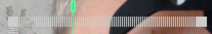
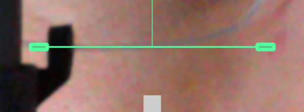
Determining height - right & left
Determine the height by moving the needle (horizontal line) to the bottom inner edge of the spectacle frames.
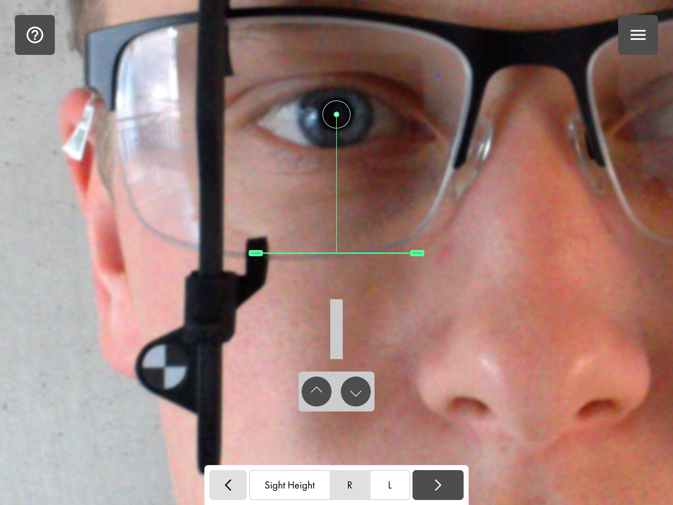
Pointers/Ruler: By touching the needle, you can roughly move the vertical axis in the direction of the inner edge.

Arrow keys: By tapping the arrow keys, the inner edge can be exactly determined vertically in even finer steps.
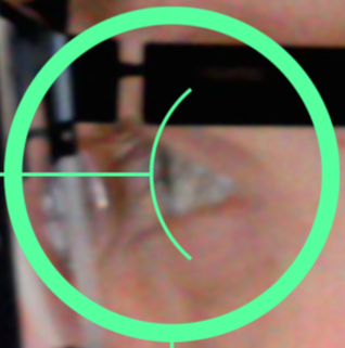
Determining the corneal vertex
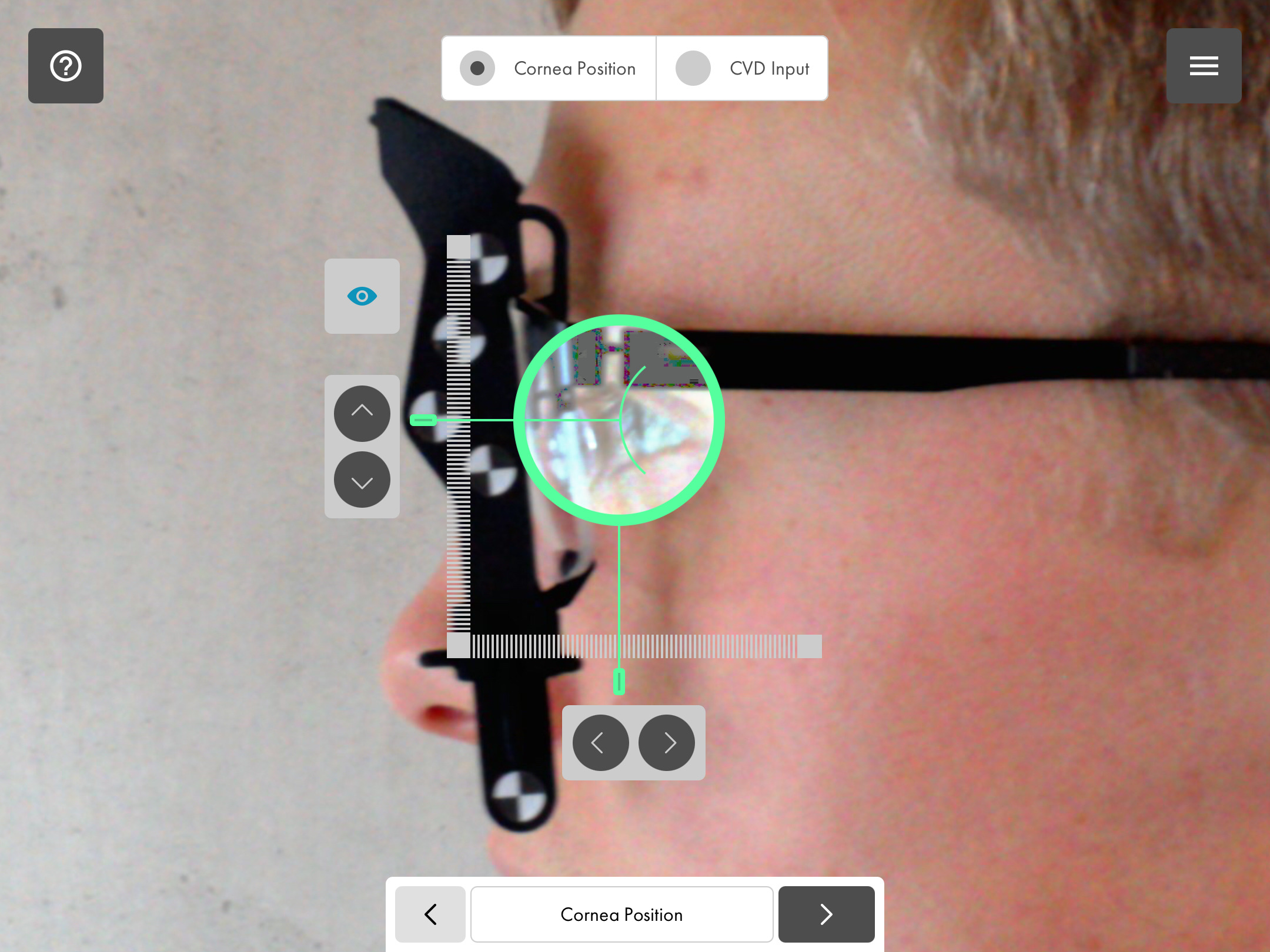
The corneal vertex is determined by positioning the lowest point of the green cup on the outermost point of the cornea.
Cup: By touching the cup or its direct vicinity, you can simultaneously move its position horizontally and vertically.
Pointers/Ruler: Alternatively, you can roughly move each of the needles in the horizontal or vertical axis in the direction of the cornea by touching them. By tapping directly on one of the rulers, the corresponding needle jumps to the position touched on the selected axis.
Arrow keys: By tapping the arrow keys, the position of the corneal vertex can be exactly determined horizontally or vertically in even finer steps.
Note: Depending on the height or positioning of the temples on the spectacles, the customer’s eye can be completely or partially concealed in the photo. In this case, please estimate the position of the cornea and position the cup accordingly. Then, validate the plausibility of the vertex distance manually.
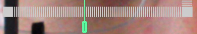
Determining the spectacles' wrap angle
In order to determine the spectacles' wrap angle, the frames are placed on the tablet with the top side facing down and with their front facing you.
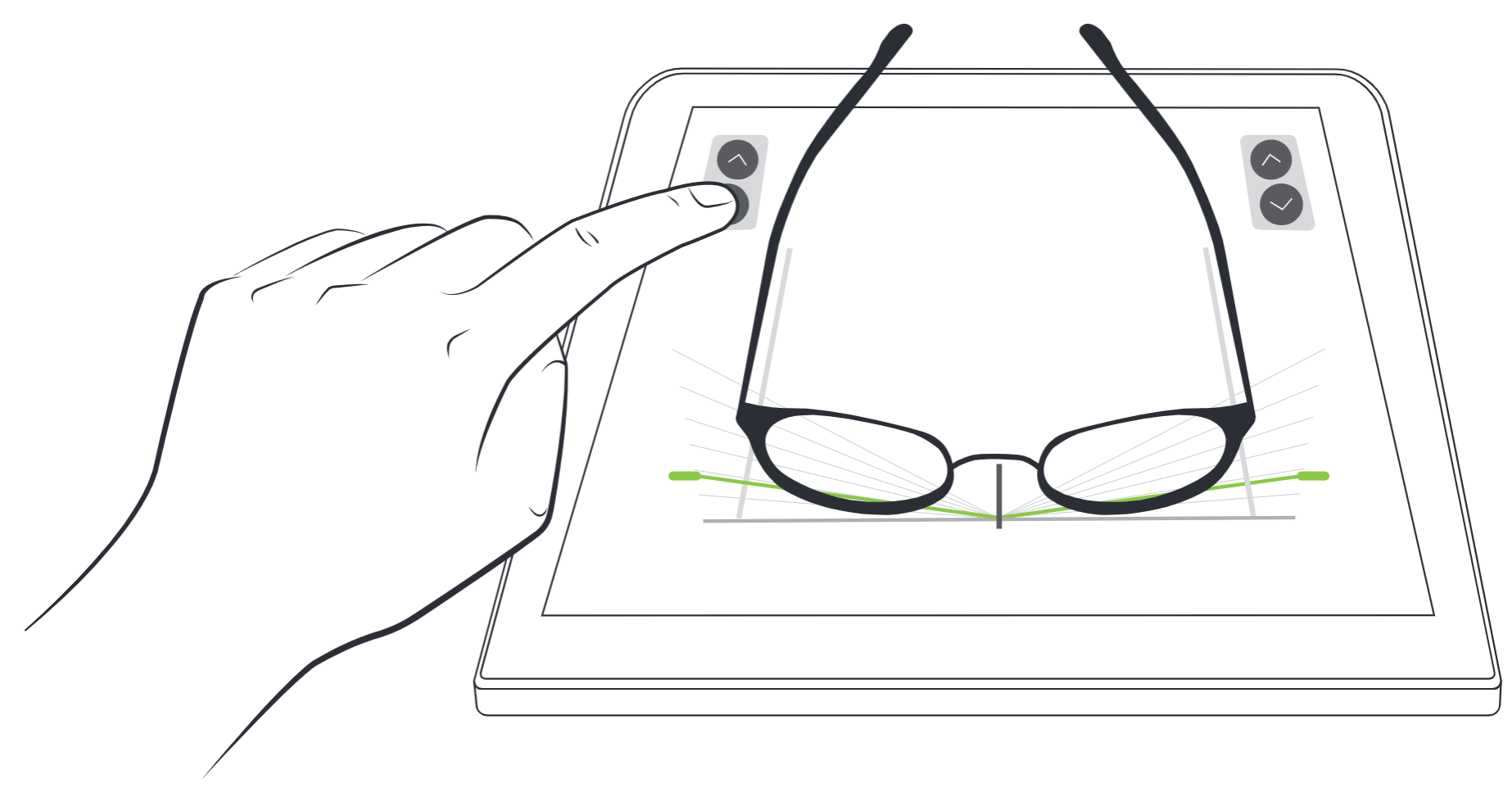
- Please observe that the front of the spectacles is positioned flush and parallel to the stop edge and align the centre of the bridge of the spectacles with the centre indicator. Check whether both temples are positioned as flush and parallel to the lateral edges as possible.
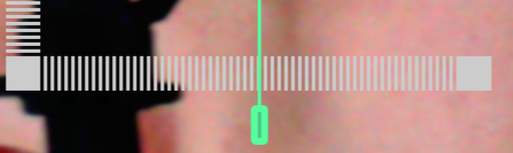
- The frame wrap angle is determined by moving the pointer left or right, so that the beam touches the foremost point of the temples.
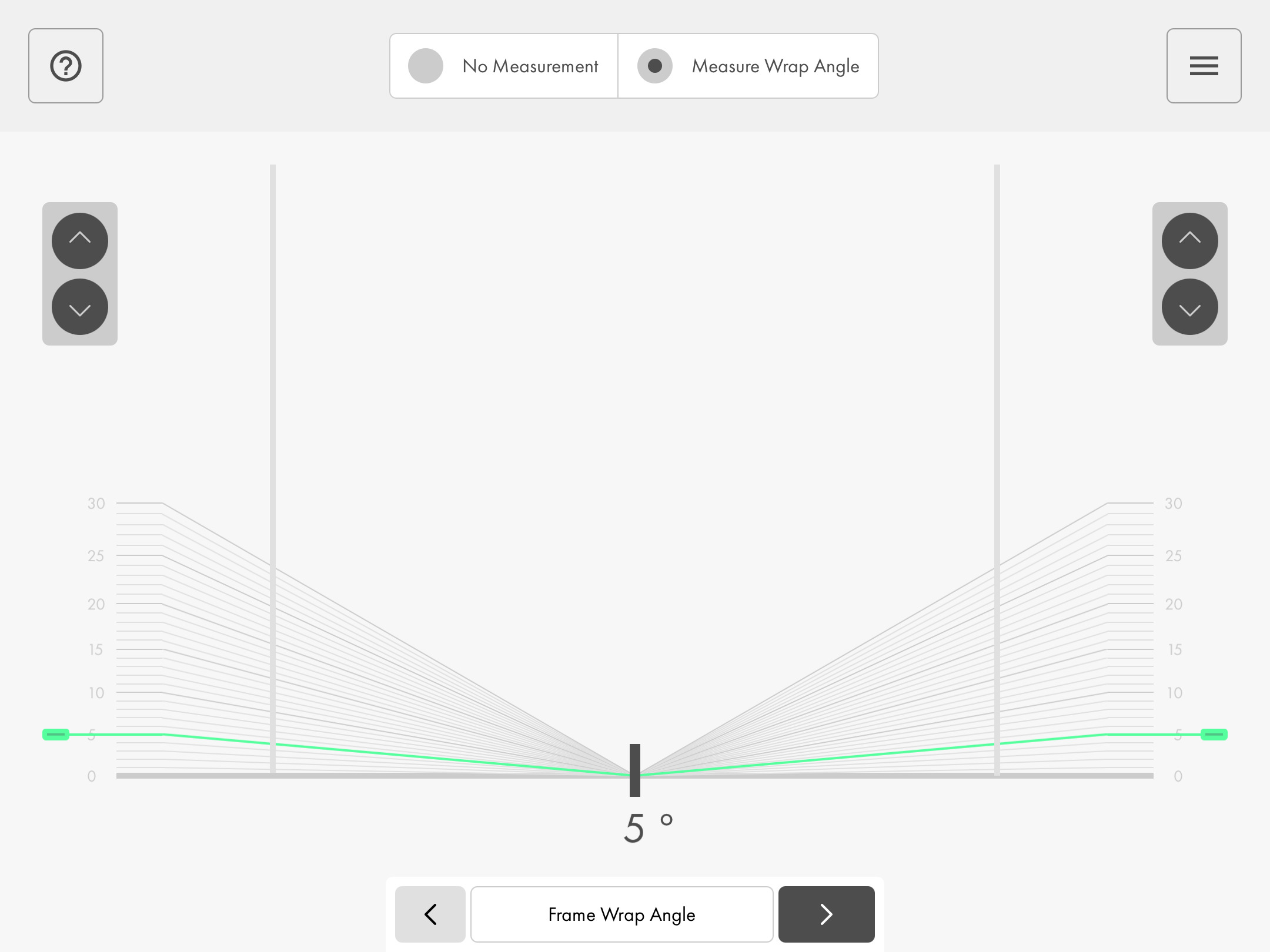
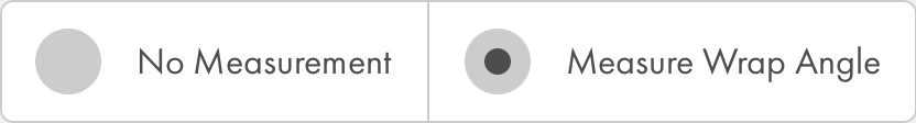
No measurement / Measuring the frame wrap angle: Activating/deactivating control elements to determine the frame wrap angle.

Beam/Pointers: With the pointers left and right, the bear or the pointers are moved up or down or the frame angle is decreased or increased. By tapping the scale, the beam or the pointers can directly jump to the area touched or directly to the indicated angle.

Arrow keys: The frame wrap angle can be precisely determined in 1° steps using the arrow keys.
Completing the measurement
In the conclusion process, the values determined by the software can be checked, corrected and then, be transferred to the demo lenses with the help of the template.
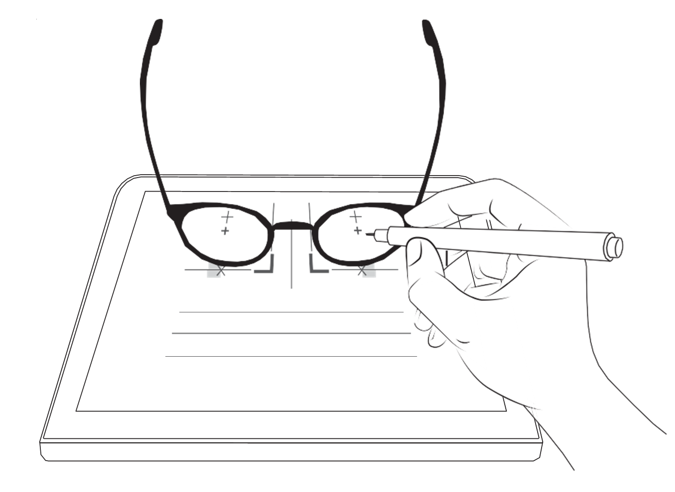
- You can determine the optimal visual point by placing the spectacles on the screen with the demo lenses. The lock can be used, to avoid unintentional inaccurate entries by touching the surface. Then, align the spectacles with the indicated template. Align the centre of the bridge of the spectacles with the centre indicator. Align the inner edges of the lenses flush with the inner edge indicators of the template.
- Apply light pressure to the spectacles, to ensure they are positioned flat on the surface. Then, using the overhead marker, mark the visual point on the demo lenses required for production (zero line of vision or principal line of vision).
- Give the customer the spectacles. With the customer wearing the spectacles, check the condition of the marked position on the lens compared to the actual position of the customer’s pupil in accordance with the dialogue guide.
- If the marking requires correction, kindly ask the customer to give the spectacles back to you. Then, unlock the software’s user interface by tapping on the lock button again. Change the values at your own discretion and restart the transfer process via the updated template.
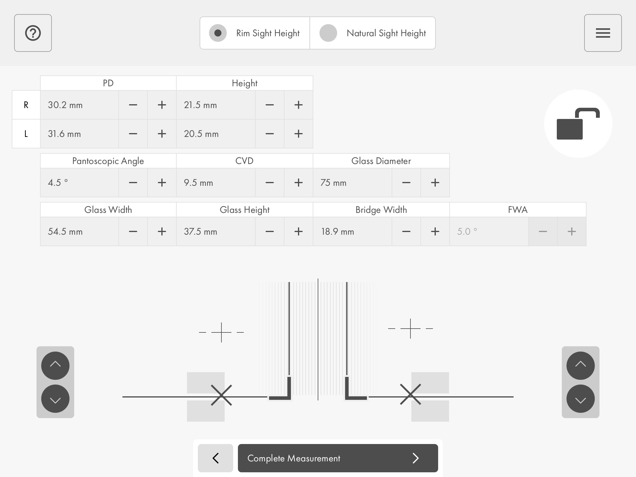
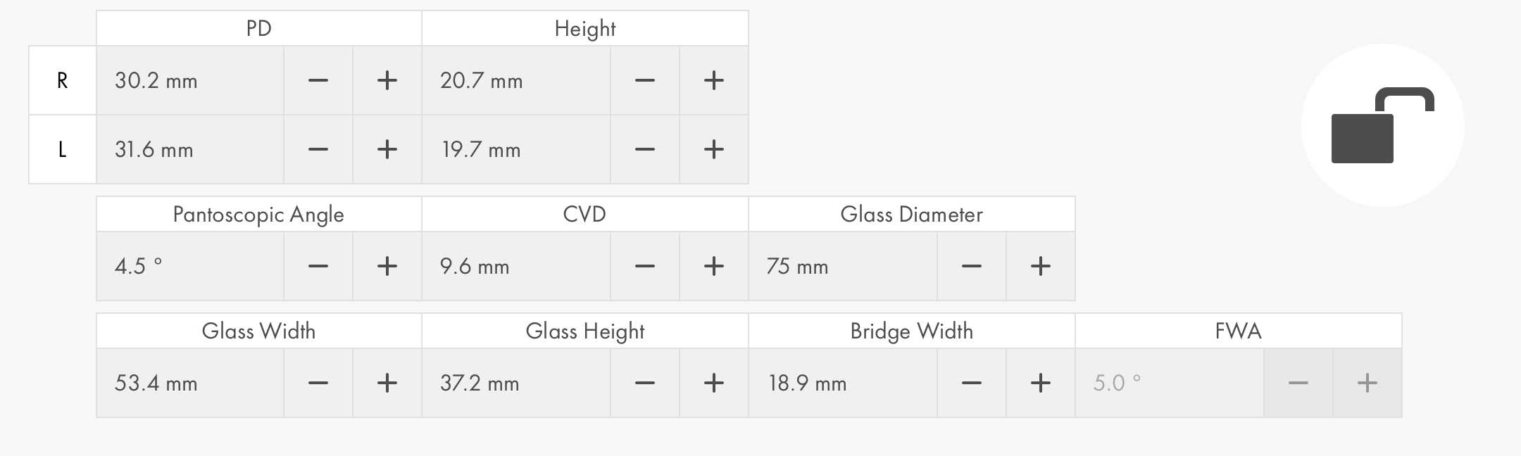
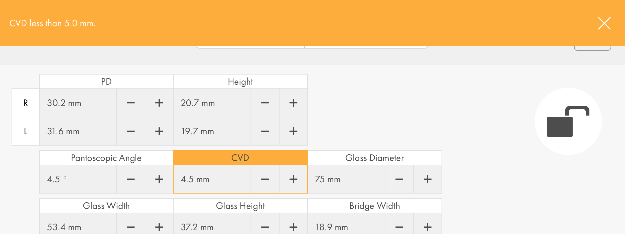
Specification of the centration (centration values)
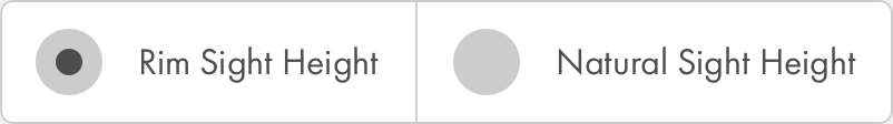
Zero line of vision / principal line of vision: You can switch back and forth between the values for zero or principal line of vision here.
Buttons and functions:

Lock: Lock/unlock by tapping on the surface.
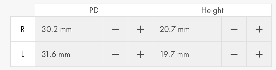
Plus/Minus: You can decrease or increase individual measurements in 0.5 mm steps with this. The first time it is modified, it will round up to the nearest 0.5 mm increment.
Centration template
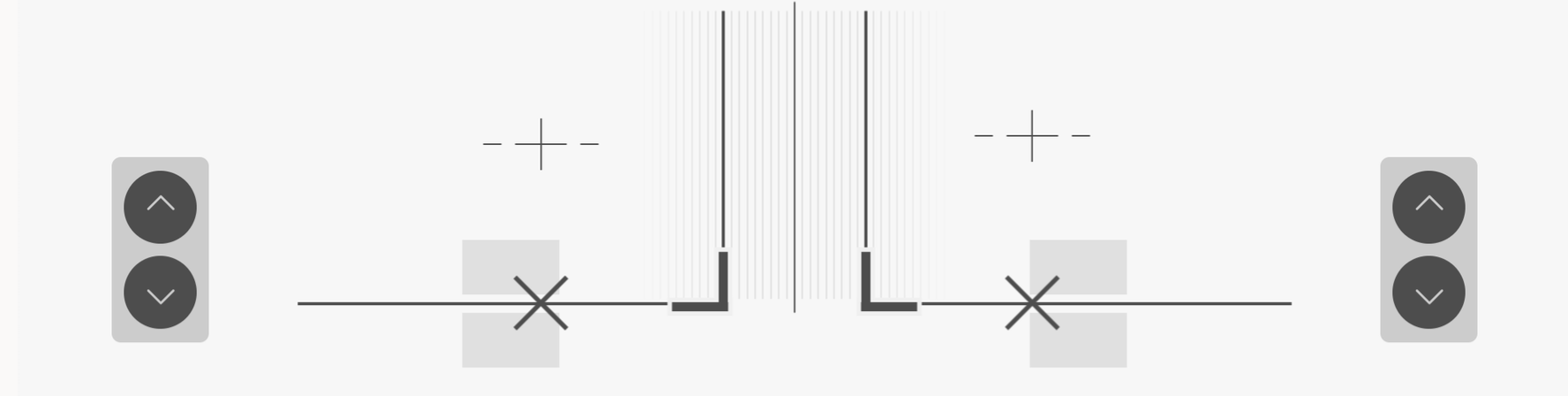
Buttons and functions:
Visual mark: Marking the zero line of vision.
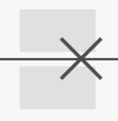
Centration aid and measuring point ( x ) to the sight height (Rim system).
Arrow keys: By tapping the arrow keys, the position of the measuring point ( X ) can be exactly determined vertically.

Complete: Complete centration for customer and spectacles.
Warnings and error messages
Warnings
The software points out unusual or peculiar measurement data. These warnings are merely intended to assist you like this:
The final assessment and possible correction of the measurement is of course your responsibility.
List of possible warnings:
- PD left seems very low.
- PD right seems very low.
- PD left seems very high.
- PD right seems very high.
- Significant difference between PD left and right: more than 3 mm.
- Vertex distance shorter than 5 mm, vertex distance longer than 22 mm.
Error messages and troubleshooting
The software generates messages for certain events that indicate incorrect operation on the part of the user or incorrect execution on the part of the software.
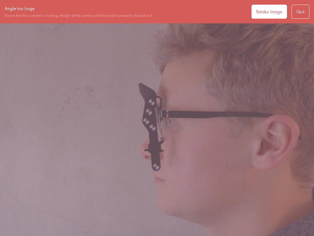
These error messages are always displayed textually at the top of the screen and are indicated by a clear red coloring of the entire screen, for example:
The following information and error messages may appear. Please carry out the instructions described for the respective case in order to remedy the problem:
| Error message | Troubleshooting |
|---|---|
This device is not supported. |
Please contact your IT support. For information on devices currently supported by Qvido, please visit Systems Requirements |
An error occurred during installation. |
For support in remedying the problem, send us an email. |
The camera is not ready. |
Please wait a moment and try again. |
Access to the camera is switched off. Please allow access; see the instructions. |
Access to the camera is currently disabled in your iPad’s settings for the Qvido app. Please open the “Settings” app in the iPad and select “Qvido” from the list on the left-hand side. Then switch the “Camera” to “On.” |
You were too close to the customer when the image was taken. |
The necessary distance to the customer was not maintained. Please take the last image again while maintaining the prescribed distance: Front view: 30–50 cm Side view: 40–60 cm |
You were too far away from the customer when the image was taken. |
The necessary distance to the customer was not maintained. Please take the last image again while maintaining the prescribed distance: Front view: 30–50 cm Side view: 40–60 cm |
It was not possible to delete the measurement. |
Please try to delete it again. If the problem persists, send us an email. |
Error during image analysis. |
Please take the last image again. |
Data transfer via Wi-Fi failed. |
The measurement data could not be transferred. Please try again. |
Please take the last image again. |
Make sure that the customer and tablet approximately form an axis or are aligned perpendicular to one another. |
The angle between the customer and tablet camera was too large. |
Make sure that the customer and tablet approximately form an axis or are aligned perpendicular to one another. |
Error when taking the image. |
Please take another image. |
Error when continuing the measurement. |
A measurement that was previously started could not be restored and was deleted. Please start the measurement again. |
The fitting frame was not detected. |
Make sure that the customer and tablet approximately form an axis or are aligned perpendicular to one another. |
Internal error. |
For support in remedying the problem, send us an email. |
Unexpected error. |
For support in remedying the problem, send us an email. |
IT security
The Qvido app runs locally on the corresponding iPad and does not store any data. No personal data is collected or stored when the system is used. After the system is done being used, all of the determined values and photos are always deleted. No backups are created.
If automated transfer to an external system is used, it is the responsibility of the external system to ensure that IT security and data protection requirements are maintained outside of the Qvido app.
Requirements for the IT environment
The current requirements for the IT environment are described here: Systems Requirements
Measures to be performed to ensure IT security
Please make sure that the iPad with the installed Qvido app is connected to a network that can only be accessed by internal employees.
Procedure for lost or stolen authentication elements
Make sure that the authentication elements (access data) provided by Oaktree are only accessible to authorized persons. If it comes to your knowledge that unauthorized persons have gained access to this information, please notify your IT department and the manufacturer of this immediately. Oaktree Technologies will block the affected access details and provide new ones.
Cleaning and disinfection
Clean the fitting frame thoroughly by wiping and disinfecting it before and after each use. Wear personal protective equipment while doing so (heavy-duty gloves, water-repellant gown, face mask, or protective goggles and a mask).
When cleaning the fitting frame, use a non-protein-fixing disinfectant with cleaning effect that is registered with the German Association for Applied Hygiene (VAH) for wipe-down cleaning and disinfection on the basis of alcohols and quaternary compounds (e.g., CaviWipes from Metrex), fully demineralized water (demineralized water that is free of facultative pathogenic microorganisms as per KRINKO/BfArM recommendations), and a lint-free cloth (e.g. Braun Wipes Eco).
Complete the following steps each time before and after using the fitting frame:
- Wipe down the product thoroughly, using sufficient disinfectant wipes to disinfect the surfaces.
- Make sure that you reach all surfaces as well as any grooves and notches on the product and that they are fully covered with disinfectant during the disinfection process.
- Let the disinfectant take effect for the treatment time specified by the manufacturer of the disinfectant.
- Moisten a lint-free cloth with demineralized water and use it to thoroughly wipe down the product to remove any remaining disinfectant.
- Dry the product with a lint-free cloth.
Servicing/maintenance
Oaktree Technologies provides updates for the Qvido app at regular intervals. The download and installation of these updates are carried out automatically depending on the update mechanisms that are generally defined on your iPad. To ensure that these mechanisms work, the tablet must be regularly connected to the Internet via a network connection.
Uninstalling and disposal
Uninstalling the app
If necessary, the Qvido app can be uninstalled via the general uninstallation mechanisms provided by Apple iOS. Follow your iPad’s instructions for uninstalling apps. All data and information relating to the app are also deleted when the app is properly uninstalled.
Recycling and disposal of the fitting frame
The fitting frame is made of polyamide (PA6) and can be recycled in accordance with recycling code 07 for polyamide.


Please remove all rubber parts (upper and lower rubber sleeves) prior to recycling. These are made of polyurethane (PUR) and cannot be recycled. The rubber sleeves can be disposed of in normal household waste.
Technical specifications
Performance data and measuring accuracy
The Qvido app supports opticians in determining the following optometric centration data with the specified possible precision:
| Value | Precision |
|---|---|
Pupillary distance – right |
0.1 mm |
Pupillary distance – left |
0.1 mm |
Fitting height – right |
0.1 mm |
Fitting height – left |
0.1 mm |
Corneal distance |
0.1 mm |
Pantoscopic angle |
0.1 degree |
Frame wrap angle |
1 degree |
Lens width |
0.1 mm |
Lens height |
0.1 mm |
Lens diameter |
5 mm |
Communications interfaces and protocols
For information on communications interfaces and protocols, please see: URL Scheme
Materials in the fitting frame
The fitting frame is made of the following materials:
- Fitting frame and lock slides: TEKUMID B H9 GK6 LW (Tekuma)
- Rubber sleeves: Elastollan 1180 A (BASF)
All of the materials used are verified biocompatible in accordance with ISO 10993.
Symbols used
| Symbol | Meaning |
|---|---|
|
Caution: potential danger that could result in minor or moderate damage |
|
Manufacturer |
Contact and support
You need support or have a question regarding Qvido made by Oaktree?
Please get in contact with us via email.